This is for setting up the X Carve machine at the shop in your own Easel account. Even if you use a shop computer, the machine configuration is done in your personal account.
First, you need to create an Easel account at Inventables. Once you have created your Easel account and you get to the screen where you can set up a new project, you need to click the Machine menu item and click the Set up new machine button.
The next screen will ask you which CNC version you have. Choose X-Carve (pre-November 2021).
Choose these options on the Enter your machine details page:
Motion Controller: X-Controller
Rail size: 1000mm x 1000mm
Z Axis: Belt Drive w/ ACME threaded rod
Spindle: DeWalt 611
Belts: 2GT 6mm
Dust shoe: Yes
You will either need to already be connected to the CNC via USB when you click the Confirm settings button, or it will prompt you to connect.
The next screen is asking you to confirm that everything is moving the right direction. Click each one of the large blue arrows with the +/- signs in them. Watch the machine to see that everything moves the correct direction. If so, then click the 3 Yes boxes under the question, Working correctly?. Then click the Continue button.
The next screen is asking if you have homing switches. The answer is yes. Click that button and go to the next screen which will actually home the machine when you click the Start homing sequence button. Be prepared to hit the large red button on top of the control box if something seems to be wrong when the homing starts.
The machine will move the router to the top of the Z axis. Then it will move to the left of the X axis. Finally it will move to the front of the Y axis.
The next screen asks if you have a Z probe. The answer is Yes.
The probe is a brass disk that has a wire connected to a spring clamp. You can see it in the picture above. You should be able to find it in one of the accessory boxes on or near the machine.
The next screen asks you to plug the Z probe leads into the carriage. This is the red and black wires with the barrel connector. It will plug into the right side of the Z axis carriage.
Plug the barrel connector into the jack and clip the spring clamp to the collet.
The spring clamp is the clip it is telling you to connect to the collet. Click the blue Clip is attached button.
Touch probe to bit.
The next section is asking you to touch the plate to the collet (or you can touch it to the bit). Once you make contact with the bit or collet, you can hit the final Continue button
The machine is almost set up in your Easel account and ready to start using.
One More Thing
There is one other step you need to do to complete the machine configuration.
Got to the Machine menu and click the Edit you machine box. It will bring up a dialog box. What you need to change is in the image below.
By default the Spindle Controlled by will say Manual. You need to change that to say Hardware. Then save the configuration with the Save button.
Now the machine is configured in your account and you are ready to get started.
Here are some settings and general information for the Morristown Makers’ vinyl cutter. The machine is a Seiki SK-870T and we are driving it with Inkscape using the Plot extension. Other cutting software may work for the machine, but you will have to do some testing on your own to get it working.
This information is not intended to be comprehensive. It is expected that you have received training on using the machine before this information will be helpful.
Controls
Power and USB
The power plug is on the left side of the machine along with the ON/OFF switch.
On the right side is a serial and USB port. Through testing, it seems that the machine works better while using a USB to serial cable plugged into the serial port. There is one attached to the cutter. Please do not remove the cable as it needs to stay at the shop with the machine.
Speed and Force
The speed and force of the cut are controlled by the arrow pad on the right side of the top of the machine.
The speed is controlled by the up and down arrows. This should be about 300 mm/sec. This seems to work well on normal vinyl cuts. There would be value in testing different materials and speeds to see what are appropriate speeds for different materials.
Force is controlled by the left and right arrows. 70 to 90 grams of force seems to work well with normal outdoor vinyl.
Loading Material
Lift the lever on each pinch roller and slide the vinyl under the rollers. The levers should be raised each time after using the machine. This prevents flat spots on the rollers.
Slide the material through the pinch rollers and line it up straight. There are alignment lines you can use to set the right edge of your material correctly. (This is explained clearly in class).
Adjust the pinch rollers to about 1″ from the outside edge of the material and the third roller approximately in the center of the material. Be careful to avoid setting a pinch roller in the center of the machine where the two knurled rollers come together.
Orienting Cutter Head
Using the control panel of the cutter, press the Leave button. This allows the arrow buttons to move the cutter head into position. Place the cutting tool to the bottom right of where you want the machine to cut out your artwork.
After getting the tool in place, press the Origin button. This will take the machine out of move mode and set the origin position. You should be ready to send the job from Inkscape and start cutting.
NOTE: In testing, it seems that the machine is more consistent with making proper cuts if you hit the Origin button at least twice after setting the cutting position.
Sending the Job from Inkscape
After the artwork is prepared in Inkscape, it is time to cut. A quick look at View | Display Mode | Outline inside Inkscape will show what will be cut in the next steps.
Extensions | Export | Plot is the menu item that will get you started in sending the job to the vinyl cutter. However, before you can cut, you need to make sure your Inkscape is configured with the correct settings.
Connection Settings
Most of this first screen will not need to be changed. The most important settings to choose are:
Port type: Serial
Serial baud rate: 9600
Serial byte size: 8 Bits
Serial stop bits: 1 Bit
Serial parity: None
Serial flow control: Hardware (DSR/DTR + RTS/CTS)
Command language: HPGL
The Parallel and Serial port information will be specific to your computer. Our cutter does not use a parallel interface. The actual serial port number may change if you have another USB device plugged in when using the cutter.
For a Windows machine the serial port will be something like COM1. For Linux it will be similar to /dev/ttyUSB0. I am not certain on a Mac. I would be glad to work with someone who has a Mac to see if we can get it configured.
Plotter Settings
Default X and Y resolution is 1016. You should not need to change these values. The Pen number is used when using layers to distinguish different colors of vinyl for a layered job. This is not something we will cover in class. Pen force and Pen speed do nothing on our cutter.
Rotation
The degrees of rotation are used to turn the art in various orientations for cutting. Normally you will want this to be 90° or 0°. To cut the art in the orientation you see on your Inkscape screen, change this setting to 90°. At 0° the artwork will cut front to back (rotated 90° counter-clockwise from what’s on screen).
Mirror
Mirror on X axis will flip your artwork from left to right. When rotation is set to 90° (what you probably want it to be most of the time), this is used to create a sticker that can be put on the inside of glass and seen properly from the outside. Mirror on Y will do the same (except flipping the art front to back) with the same results when rotation is set to 0°.
Center point at zero is used when you want the cutter’s origin to be the center of the artwork instead of the bottom right corner. This is probably never what you want for a vinyl cutter.
Plot Features
This tab can be left default for good cuts. However, these settings can be adjusted if you find a special case where they can help.
Apply / Cut
Hit the Apply button to send the job to the cutter. Enjoy your cut piece!
Paying for Vinyl
We charge $2 per foot of the 24″ wide vinyl. This is the vinyl that is owned by the shop and available for your use. All other vinyl at the shop belongs to another member and should not be used without permission. You are welcome to bring your own vinyl to cut on our machine.
Here is some follow-up information for those who took the laser class and would like to use the laser. Some of these items were mentioned in the class, others will be new information.
Software
There were two pieces of software mentioned in class. The first was the graphics software used to create the image file the laser needs: Inkscape. The second is the laser control software: K40 Whisperer.
Inkscape
Inkscape
In class we showed Inkscape as the software that was used to create the images. For the laser, the images need to be saved in SVG format (Inkscape’s native format), or DXF.
There are other graphics programs that can create the needed SVG files (scalable vector graphics). CorelDraw, Adobe Illustrator, Affinity Designer—as well as many others—are alternative tools you can use if you already have one of them installed. Inkscape is free and, while not always the easiest to use, it is not much harder than many other full-featured vector graphics program.
There are many tutorials online for using Inkscape, but I would start by watching the videos made by the creator of K40 Whisperer because he teaches what is needed to make the graphics for the laser.
K40 Whisperer
This is the laser control software. It works well with our laser and we will soon have a computer in place at the shop that will control the laser and you won’t have to configure the software on your own machine. But, until we have that computer set up, you can work through the setup steps on the K40 Whisperer website to get started on your own machine if you would like. When I was setting up the software and laser at the shop, I believe everything was left at default settings that the software and website recommended.
Don’t miss his tutorial videos towards the bottom of the software page. They are short and very informative.
Laser Setup
Turning Everything On
[This section will be updated as the physical location and setup of the machine changes in the coming weeks]. The laser should be plugged into a power strip. When turning the strip on, everything that needs to run for the laser to work, should come on. But, here are the things to check if something doesn’t seem right.
The Main Machine: If the on/off switch on the laser control panel doesn’t light up, then switch it to the on position.
Water Pump: There is a pump submerged in a bucket of water under the laser. Two hoses are in the bucket. One comes out of the pump and sends water to the laser. The other comes from the laser and is not connected to anything in the bucket. It is the return water from the laser unit. It would be wise to check and make sure water is pumping when you get started.
Air Assist: We did not have this in place during class, but we are working on an air assist nozzle. It pumps air right at the base of where the laser is cutting. It, along with the fan for smoke exhaust, are needed to help get the cleanest possible cuts with as little flame as possible. This is the stand-alone pump that makes so much noise.
Smoke Exhaust: Smoke from the laser is pulled from the unit to a filtered box by a fan. This should be running when you use the laser. It will keep the smoke fumes down in the room as well as give you a much better cut.
Settings
These are the items that you can adjust as you are using the laser. If you are not getting the cut you expect, go through this list and make sure everything is adjusted properly.
Focus
Use the “Laser Focus Block” to help set the height of the bed to the laser output lens. If the block cannot be found, the proper distance is 1-15/16″ to 2″ from the bottom of the laser lens to the work piece.
Raise and lower the bed using the knob on the front of the machine. Be aware that the table currently does not rise perfectly level. You may have to focus one end of the table to the laser and then check the other end. Adjust the table as necessary.
Laser Strength
The laser strength is set by the knob labeled “current regulation” on the main control panel to the right of the laser. You will need to make some test cuts and engravings to find what works best for your project and material.
Though I haven’t confirmed the exact number, the laser should not be set to greater than 15 mA on the “current indication” meter if it is running continuously. If it is pulsing a bit above 15 mA, that should be fine.
Be aware that the laser will wear out faster and need replacing the more it is run closer to 100% power (which is approximately 15 mA on the meter). Cut and engrave at the power needed, but try not to overdo it. Realize that for some materials you will have to run the cutting pass multiple times to get a cut all the way through.
Speed
K40 Whisperer Speed Settings
This is a setting inside the K40 Whisperer software. At the bottom left you will see a speed in mm/sec (or inch/sec if you choose inches as your default units when setting up the software). Since the laser will have a static strength (based on the power knob setting), the depth/strength of cut is determined by how quickly the laser moves over the material being cut.
Graphics Colors and Meaning
When you create your artwork for cutting/engraving, be aware of the following colors. The colors in the art help the laser control software know how to handle each part of an image.
Red: Vector Cut
Anything you want cut all the way through should be outlined in red. You can change the speed based on the thickness of material, but it should be somewhere near the default speed of 10 mm/s.
Blue: Vector Engrave
Anything that is blue in your image will get outlined with a vector engrave. This is a burn on the surface, but not a cut (unless your power is too high or your speed is too slow). Note that this will only draw the outline of each item in blue. It will not color in the entire blue object. That is what the raster engrave (next) does.
Black: Raster Engrave
Raster engrave is where the laser burns the surface of the material being engraved. This is done in a series of lines moving left and right, then top to bottom. Anything that is black in the art will be filled in using a fast movement of the laser for the purpose of scorching the surface of the material without cutting through.
Suggestions
I recommend you watch the tutorial videos at the bottom of the K40 Whisperer website. Working through those while sitting at the laser will really teach you most of what you need to know to operate the laser confidently.
Doing these two things will help you learn how to operate the laser when you want to step out of the realm of having someone hold your hand through a project.
These are settings (or ranges) that work well with the Morristown Makers 3D printer. You are welcome to deviate from these settings for testing, but it is recommended that you change one parameter at a time so that you know the effect each change has.
Printer-Level Settings
These are the sections and settings inside Cura 4.1. You should only need to set this up one time in your slicer and then never have to change the settings for this printer in the future.
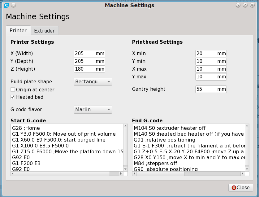
Printer Tab
Printer Settings
X, Y, Z: 205, 205, 180
Build plate shape: Rectangular
Heated bed: Yes
G-code flavor: Marlin
Printhead Settings
X min: 20 mm
Y min: 10 mm
X max: 10 mm
Y max: 10 mm
Gantry height: 55 mm
Start and End G-code Settings
These are the settings that were in use when the printer was donated to Morristown Makers. You can change the start and end G-code as needed. Or, you can use a generic start and end code.
Start G-code:
;*** Start Dual Nozzle/Bed Preheating *** M140 S{material_bed_temperature_layer_0} ; start preheating the bed M104 S{material_print_temperature_layer_0} T0 ; start preheating hotend G28 ; home M190 S{material_bed_temperature_layer_0} ; heat to Cura Bed setting M109 S{material_print_temperature_layer_0} T0 ; heat to Cura Hotend ;*** End Preheating *** G92 E0 ;Reset Extruder G1 Y3.0 F500.0 ;Move out of print volume G1 X60.0 E9 F500.0 ;start purge line G1 X100.0 E8.5 F500.0 G1 Z15.0 F6000 ;Move the platform down 15mm G92 E0 ;Reset Extruder G1 F200 E3 G92 E0 ;Reset Extruder
End G-code:
M104 S0 ;extruder heater off M140 S0 ;heated bed heater off (if you have it) G91 ;relative positioning G1 E-1 F300 ;retract the filament a bit before lifting the nozzle, to release some of the pressure G1 Z+0.5 E-5 X-20 Y-20 F4800 ;move Z up a bit and retract filament even more G28 X0 Y150 ;move X to min and Y to max endstops, so the head is out of the way G92 E0 M84 ;steppers off G90 ;absolute positioning
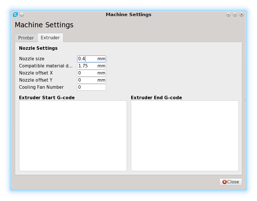
Extruder Tab
Nozzle Settings
Nozzle size: 0.4 mm
Compatible material diameter: 1.75 mm
Nozzle offset X: 0 mm
Nozzle offset Y: 0 mm
Cooling Fan Number: 0
Per Model Settings
The per-model settings can be downloaded and imported into Cura as a profile. This was exported from Cura 4.1, but you should be able to import it into the current Cura version. Unzip the the archive and import the .curaprofile into Cura.
Layer Height
0.1 to 0.2
0.16 seems to be a good compromise between speed and quality.
Initial Layer Height
0.16: This should always be 0.16 regardless of the layer height you set for all the other layers.
Line Width
0.4: This is the nozzle diameter. You can adjust this up and down a little, but generally it should not be changed. This is typically always set to your nozzle diameter.
Shell Thickness
Wall Thickness
0.8: This means 2 outside perimeters. You can increase this in 0.4 mm increments (i.e., 0.4, 0.8, 1.2, 1.6, etc.).
Top and Bottom Thickness
0.8: This is determined by how many solid layers you want on top and bottom multiplied by your layer thickness. If you are printing 0.16 layers and want 5 solid top and bottom layers, you will have a 0.8 mm thickness.
Retraction
Yes: Enable retraction almost always. Flexible filaments print better without retraction.
6 mm
Infill Density
25%: This can go up or down depending on your needs. But 25% is a good mix between strength and speed.
Temperature
Printing Temperature (Hotend)
205° C: This is material specific. Different filaments (even regular PLA from the same manufacturer) will need different temperatures. Generally, all the PLA used on this machine prints well in the 205° range. Adjust as necessary.
Build Plate Temperature (Heated bed)
50° C: Technically PLA does not need a heated bed. However, having some heat on the bed seems to help with adhesion.
Print Speed
30-60 mm/s: There is a marked quality difference between 30 and 60 mm/s (slower is better). However, you can expect that it will take approximately twice as long to complete a print at 30 mm/s as it does 60 mm/s.
Recommended 50 mm/s: This printer can print accurately up to 70 mm/s but quality suffers.
Cooling
Enable Print Cooling
Yes
Fan Speed
80%: Faster than this and the hotend struggles to stay up to speed. And, at 80% it cools sufficiently.
Supports
Depending on your needs
Build Plate Adhesion
Depending on needs, but a skirt of at least 1 perimeter is recommended to help prime the printer.
Here are some links that might help you in learning more about building foam board airplanes. These are some of the things mentioned in class as well as extra resources that will help you in building other planes.
For the most part these are resources that will help you in building Flite Test plans. However, many of the skills learned in printing and building their planes will be useful when building other models out of foam board.
Printing Plans
Printing the plans can sometimes be difficult to get right. I have found that these instructions by SP0NZ always work for me. SP0NZ, by the way, is the guy who did the layout work for many of the planes that Flite Test creates.
The FT Tiny Trainer is the plane we built in class. You can download the plans from the linked page by going to the “resources” tab in the middle of the page. You can get some written instructions on the build process from their website. Also the build video can be seen below.
This is a companion post to the paper instructions we are handing out at the 2019 Kingsport Mini Maker Faire. If you don’t have that paper, you can download it to help you build your own infinity mirror.
Bill of Materials
The following links are samples of what is needed. Certainly there is nothing that requires these exact materials. Some of the items you can find locally or might even be able to snag for free from your home or by asking around.
The links to Amazon below are affiliate links.
LED strips
In the mirror we had at the Maker Faire we were using red LEDs. But you can choose your color to personalize the mirror the way you want. You can even buy strips that have a remote so that you can change the color according to your mood.
The strip we used in our build was 12 volt LEDs. This is the most common and generally cheaper option. You can find 5V strips that can be run with a cell phone charger. Typically they are a bit more expensive.
There are a couple of helpful things to know if you have never used LED strips before. First, they can be cut to length at the little copper pads between the LEDs. There are 3 lights per section on 12V strips and only 1 light per section on 5V strips. You must cut at the copper pads between the sections for them to work properly after cutting.
Second, you have to ensure that you have enough amperage from your power supply to power the number of LEDs. That said, for a project this size, at 12V you only need a 500 mA (or greater) current supply.
Power Supply and Connectors
12V power supply for the mirror.
You probably have plenty of power supplies in a box or drawer at home that can run this project. If you have 12V LEDs you will need a 12V supply. Make sure you have a 5V supply if you have 5V LEDs.
The power supply we are using for our project is from an old network router. There are plenty of these types of supplies to be found for $1-3 at most thrift stores.
The front of the mirror is plain glass with window tinting film applied to it. Our infinity mirror was based off the size of the glass we had lying around. It is the scanner glass from a disassembled home printer. All other dimensions for our mirror were based on that.
Alternately, you can use a one-way (also called a two-way) mirror instead of glass and tinting film. This is the type of mirror that you can see through from one side but is reflective on the other side. You can skip using the tinting film if you use one of these very expensive mirrors.
Tinting Film
There are some films that probably work better than others; however, just about any film you get will work to some degree. Even plain glass with no film will work, it just won’t look as nice.
If you have a window tinting shop in your area you might take your glass to the shop and see if they have a piece of scrap tinting film that will fit your glass. More than likely they will have plenty in a trash can.
However, if you need to buy some tint film, the more “mirrored” the reflection is, the better the effect. You can buy enough film on Amazon to do a dozen mirrors for less than $10.
Rear Mirror
Mirror sandwiched between a thin sheet of plywood and the rabbet cut into the edge of the frame. (The front of the box is facing the table below).
The rear of the box is just a regular mirror. Or, it could be another piece of glass with tinting film on it. It won’t be as reflective as a regular mirror, but it will work. You will want to add some type of backing (a thin piece of plywood will work) if you are using plain glass with tint film. A piece of plywood is also recommended (but not necessary) if you are using a regular mirror. This will help protect the back glass/mirror of your infinity mirror.
Assembly
Main Box
Cut 4 boards that are slightly larger than your front glass. Or, read through some options below to know how large your wooden box needs to be.
Assemble your 4 boards in the manner shown on the paper handed out at the Mini Maker Faire (or the PDF download). You want the box to be slightly larger than the glass and mirror you are using.
Even though we put a frame on our tinted front glass, we also cut a rabbet into the frame.
You can cut a rabbet in the box to set your front glass into. And then you can cover with some more decorative wood. That is the way our mirror is assembled. Or, you can just attach your glass to the wood and cover with a paper or wooden frame.
If you do not have a router or table saw to cut a rabbet, you could make your frame large enough that your glass can just sit inside the wooden box. Then attach some small strips of wood to the inside of the frame that the glass can rest on as you put a more decorative frame on the outside of the glass and box.
This is certainly an area where you can get creative in your assembly of the box and attaching the glass.
LED Strip
The LED strip in place. The one closest to us in the picture in the real one. The one in the back is reflected off the front tinted glass.
From the back of the box (with the front glass in place) draw a line around the inside of the box where your LED strip should be attached. For the best result your LED strip needs to be exactly centered between the glass and mirror.
The easiest way to get power into the box is through a power jack on the side or bottom. Ideally you would want to put power through the back of the infinity mirror. But that would require drilling a hole in the back mirror.
Power jack on the side of the mirror.
Our power jack is on the side of the box so that it can easily sit on a desk. If you plan to hang your mirror on a wall, you might want to put your power jack on the bottom of the box.
Back Mirror
Because this is the side that does not show, this does not have to be as pretty as the front. Whatever way you attach the rear mirror to the box, you will want to make sure it is easily removable. This is so you can get into the infinity mirror to make changes or replace LEDs if you want to put a different color light strip into the box.
Ours just has a piece of thin plywood screwed to the box between the mirror and the edge of the box. This sandwiches the mirror in place but allows easy access if something needs to be repaired or changed.
Enjoy Your Mirror!
Now it is time to enjoy your mirror. It is a simple project that is fun to show off. It isn’t too complicated of a project but it can yield stunning results. We hope you enjoyed seeing ours at the Mini Maker Faire in Kingsport.
If you are not familiar with Make: then you certainly will enjoy the flipping through the pages and getting great ideas for your next projects. Most of their articles can be found for free on their website (along with more details in some cases). However, having all the projects in a magazine format that you can scan easily helps you see which ones you might want to investigate further.
Make: certainly focuses more on technology crafts than traditional. But so many of their projects are a marrying of the two types of DIY.
If you don’t have a Jefferson County Public Library System card then you should certainly consider signing up. You are welcome to read their magazines in the library without needing a card. Jefferson County does not (at least the last time I checked) require that you be a Jefferson County resident to get a card. You just have to live reasonably close to one of the 4 libraries in their system.
The Tinkercad classes went very well this weekend. Thank you to everyone who came to the class and asked great questions. The teacher (me) even learned some new tricks.
Lessons
Tinkercad includes lessons inside the website where they walk you through some of the basics. What I showed in class were what Tinkercad calls lessons; however, they also have a projects section. The projects are much more complex, but working through one or two will help you understand more of the proper order of operations that I mentioned in class.
Keyboard Shortcuts
The keyboard shortcuts paper that I handed out in class can be found on the official Tinkercad page about shortcuts. They occasionally update the PDF on that page so that you can find the most up-to-date shortcuts there.
Video Tutorials
There is one set of tutorials that I saw when I was first trying to learn Tinkercad that helped me understand some of the more advanced techniques. Below you will find the first lesson in that 7 video series.
During class we talked about the codeblock editor inside of Tinkercad just a little. This gives you more control on going back and changing your designs without having to deconstruct the item. Below is a video that gives a brief overview of how this works. I included Chuck’s video because he is as YouTuber that I enjoy watching, but it may not be the best video on the subject. So here is a link to a group of videos about the codeblock editor inside of Tinkercad.
Again, thank you to everyone who came to class and made this class a success!